This project uses the ADC feature of a popular AVR, Atmega8.
| Atmega8 based Voltmeter Ammeter used Component List: |
| 1x Atmega8- Programmed microcontroller 1x 1×16 LCD with Green Backlight 1x High quality Veroboard 2.5?x4? 1x LM7805 5V Voltage Regulator 2x 22uF 50V Electrolytic polarized capacitor 1x 100kpF Ceramic Capacitor 2x 10K multiturn Trimmer Potentiometer 2x 10K 1/4watt Metal Film Resistor (brown, black, orange, golden) 1x 2.2K 1/4watt Metal Film Resistor (red, red, red, golden) 2x 0.25 Ohm / 5W Power Resistor |
| Voltmeter Ammeter Technical Specifications: |
| Voltage Supply: 6V – 30V Current Consumption: ~ 100mA with LCD backlight Voltage Input: 0-24V Voltage Resolution: 100mV/25mV Current Input: 0-20A Current Resolution: 800mA/200mA |
Contents
Short Note on ADC
ADC stands for Analog to Digital converter, it converts analog voltage level to equivalent binary.
Application Principle
Atmega8 has 10bit ADC which can also be used in 8bit mode for better accuracy. In this application, 8bit mode is used, so we have digital reference limits as 0(low) and 255(high).
The analog voltage reference is used at 5V here, so we get 5/256=0.01953125V resolution. We used 10K multiturn potentiometer to fine adjust the voltage divider at ADC0 with appx 5:1 division so we get 25.5V max in voltage input. Simply the ADC data is divided by 10 and we get voltage, and thus the resolution of this voltmeter becomes 100mV.
The current sense resistor used here is a parallel of two 0.25E/5W resistor totaling 0.125E/10W. So, at every Amps, there is 0.125V drop. Our setup can sense 100mV division, and hence the Ammeter resolution is 800mA.
The inetrnal factory default 1Mhz RC clock is used here, and no external crystal or resonator is used.
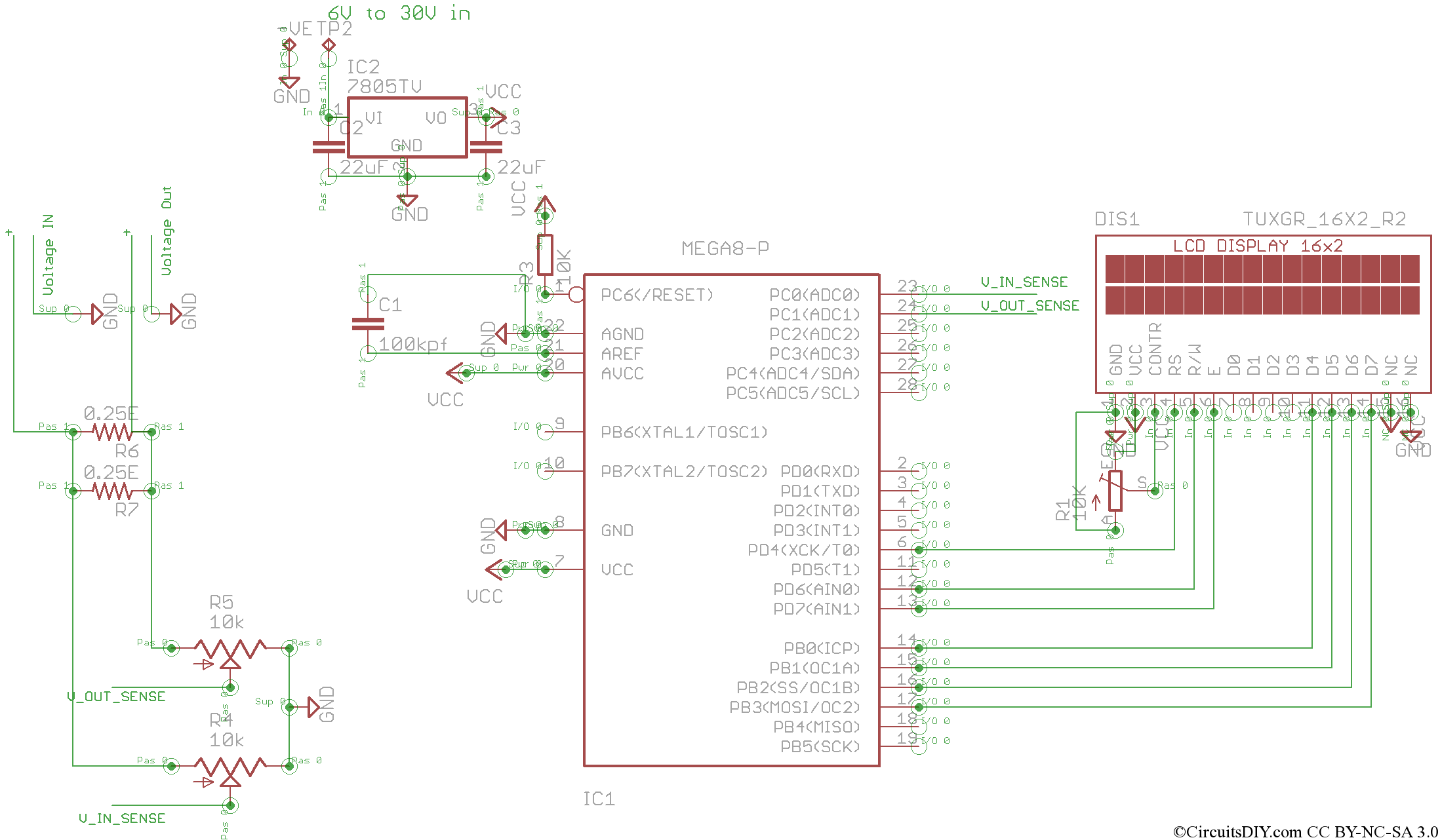
Click on the circuit diagram for high resolution picture.
- If the firmware is upgraded with 10bits ADC resolution, then the fine resolution will be 25mV and 200mA.
- If current sensing resistor used has higher value, like 1E/10W along with 10bits ADC, then Ammeter resolution will be 25mA.
Code
For developing software, I’ve used “C include file for the HD44780U LCD library (lcd.c)” by “ Peter Fleury “. The code I used is below,
#include <avr/io.h>
#include <util/delay.h>
#include “lcd.h”

uint16_t ReadVoltage(uint16_t channel);
void PrintVoltage(uint16_t voltage);
void PrintAmpere(uint16_t ampere);

int main(void)
{
uint16_t tmp, tmp1;

lcd_init(LCD_DISP_ON);
lcd_clrscr();
//Put some intro text into LCD
lcd_puts(“Volt Amp”);
lcd_gotoxy(0,1);
lcd_puts(” By Arup”);
_delay_ms(1000);
lcd_clrscr();
while(1)
{
ADCSRA = _BV(ADEN) | _BV(ADPS2) | _BV(ADPS0);
tmp=ReadVoltage(0);
lcd_clrscr();
lcd_gotoxy(0,0);
PrintVoltage(tmp);
tmp1=ReadVoltage(1);
lcd_gotoxy(0,1);
if(tmp>tmp1)
{
lcd_puts(“-”);
PrintAmpere((tmp-tmp1)*8);
}
if(tmp1>=tmp)
{
lcd_puts(“+”);
PrintAmpere((tmp1-tmp)*8);
}

_delay_ms(100);
}
return 0;
}

uint16_t ReadVoltage(uint16_t channel)
{
ADMUX = _BV(ADLAR) | _BV(REFS1) | _BV(REFS0) | (channel & 0×07);//Left Adjust
ADCSRA |= _BV(ADSC); // start conversion
while (ADCSRA & (1 << ADSC));
return ADCH;

}

void PrintVoltage(uint16_t voltage)
{

lcd_putc((voltage/1000)+48);
voltage%=1000;
lcd_putc((voltage/100)+48);
voltage%=100;
lcd_putc((voltage/10)+48);
lcd_puts(“.”);
lcd_putc((voltage%10)+48);
lcd_puts(“V”);
}

void PrintAmpere(uint16_t ampere)
{
lcd_putc((ampere/1000)+48);
ampere%=1000;
lcd_putc((ampere/100)+48);
ampere%=100;
lcd_putc((ampere/10)+48);
lcd_puts(“.”);
lcd_putc((ampere%10)+48);
lcd_puts(“A”);
}
Callibration and usage
- Connect (via switch) a 6-30V DC supply to the voltage input. this is for running the meter including the LCD.
- Connect +5V(from output of LM805) to any large pad in the bottomside, i.e, Vin(+) or Vout(+) anything and turn both presets until LCD shows 05.0V +000.0A .
- Now connect the source supply from solar panel to any pad and derive the output from any other pad, if Amps is shown as -ve when load is connected, you simply need to reverse the wires of V_In and V_Out.
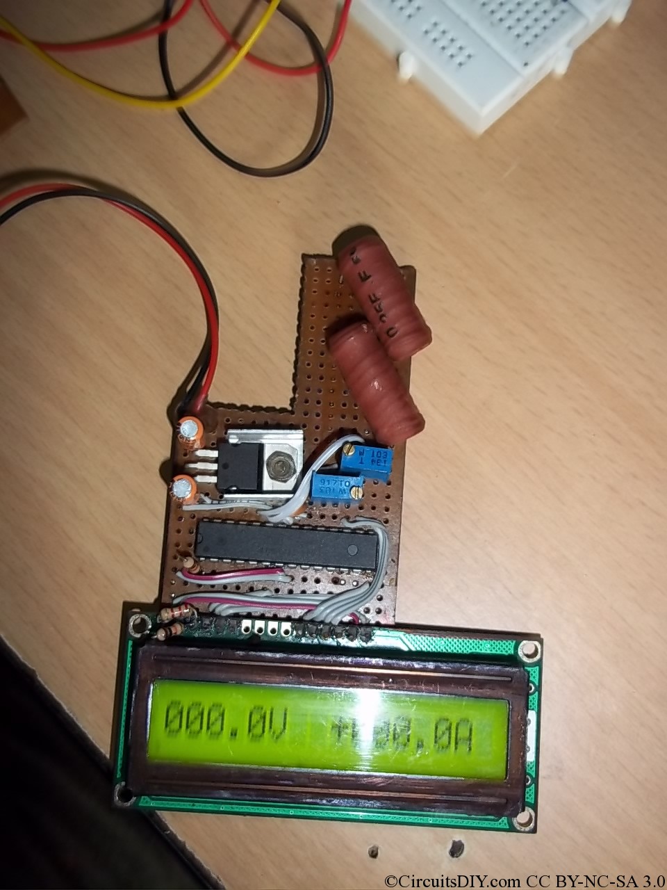
A picture of my prototype below.
Update:
New PCB here> PCB design
Questions, comments or enquiries? Drop them below.
Sir, What is the cost of ATmega8 microcontroller in India ??
It's within the 100-150 range.
How do I move the decimal point of the voltage display and current display? Is there any code to use?
I am hoping to print my voltage in 00.00V on the LCD.
Hallo,
very good work, can you help me ??? i can't find the source for compile atmega 8 can you halp me please? if you can and want sent in my email address
thank you so much for your reply.
Please have a look at the newer version of this. http://circuitsdiy.com/atmega8-based-voltmeter-ampmeter-v2
There you'll find full source code in project package.
Hi Arup,
I just wondering, why we have to multiply with 8 in this line
PrintAmpere((tmp1-tmp)*8);
Thanks
Because the drop resistor is 0.125 Ohms, then the Amperes become the potential difference multiplied by 8.
can u upload the hex file??
I'm afraid I have no copy of these old projects in my computer.
Which is the value of capacitor between ARef and GND? 100nF?
Yes.
Hi Arup,
I have build the circuit and works perfect.
For testing purpose I used and load of 10.42K.
With source a battery +9V and this load I measure 8.998 Volt and 0.012A. Excellent measure!
But,
When I connected to a solar panel (with 6 parts of 0.5V) I measure with my voltmeter 3.6V but when I connected this circuit I am getting not valid values ( +5.00V, 0.12 ...).
I ask from ADC part to make 2 measures per minutes.
Any suggestion?
The solar panel gives no standard dc voltage and the voltmeter takes the rms and show me the 3.6V?
Thanks,
I'm not really understanding what you mean and how this error occurred. What does it gives output when there is no voltage connected?
which simulator have you used for it
hi brither, how r u?
hi arup bie,
i am bejoy, u this program is great.
But some problem for me .,ple u this program convert programming languge C .Becases i work c langu.
This is already in C language.
i am getting blank on display ,i checked my hard ware all are good ,give be some suggestion for burning hex ,hope some trouble in fuse settings .
can you send me HEX with Fuses settings..thanks
It works on default fuse setting. Try to reset the circuit by shorting /RST to GND while powered on and display should come.
hii, i am using code vision for building a voltmeter can u tell me what the different in code because i cant not find #include
hii, i am using code vision for building a voltmeter can u tell me what the different in code because i cant not find
hii, i am using code vision for building a voltmeter can u tell me what the different in code because i cant not find avr/io.h
Use PN+WINAVR.
avr/io.h is a standard library so there is a problem with your IDE , I guess.
code given above is not correct thereis some error
can v use proteus software ...and avr studio