The market is flooded with cheap mobile charger circuit. Some of you may be looking for this type of charger circuit diagram and components list.
These mobile chargers uses only few parts, very simple design. But there’s a drawback too, they got damaged easily.
Some of my friends keeps asking how to repair mobile charger circuit, so I’ve decided to do a little reverse engineering of those chargers.

Cheap 220V AC mobile charger circuit diagram
First of all, lets have a look at the charger’s circuit diagram. As transformer is a bit odd, so I’ve also decided to draw it by hands.
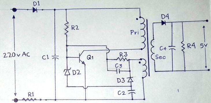
Unfortunately every charger circuit is not same, some of them contains few extra capacitors or resistors.
But even though, you can get a clear overview of the mobile charger circuit from the above diagram.
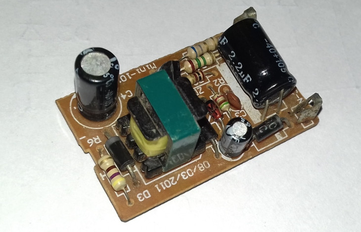
The design is quite straight forward, built on a paper phenolic PCB, could be easily repaired.
Part list of the mobile charger circuit
Finally the part list, you can replace most of them by their closest alternative.
- Q1 – 13001 transistor
- D1 – 1N4007 diode
- D2 – 6.2V Zener diode
- D3 – 1N4148 diode
- D4 – SB260 schottky diode
- R1 – 6.8 Ohm – 1/2 watt
- R2 – 1 MOhm – 1/4 watt
- R3 – 6.8 kOhm – 1/8 watt
- R4 – 330 Ohm -1/4 watt
- C1 – 2.2uF – 450V
- C2 – 4.77uF – 50V
- C3- 680pF ceramic (681)
- C4 – 470uF – 10V
As I’ve said before, this type of 13001 transistor charger circuit may vary in design and part number. But the basic circuit is same, few of them have a little LED as indicator.
Transformer details:
- Primary: Around 250 turns of 36 to 40 SWG enamelled copper wire.
- Secondary: 6 turns of 26 to 28 SWG enamelled copper wire.
- Auxiliary feedback: 8 to 15 turns of 36 to 40 SWG copper wire.
If the transformer is broken, you can use the transformer from other broken charger of similar type.
Working of mobile charger circuit
Let’s discus about how this circuit works, first have a look at the picture below.

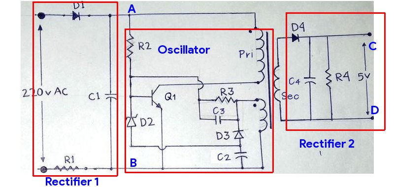
- The first stage is a half wave rectifier, made with D1, R1 and C1. It rectifies and filters the AC input to high voltage DC. So, the voltage between point A and poing B is approximately 170 volt for 120V AC input and 311 volt for 220 volt AC input.
- The Second step is a self oscillating(ringing choke converter, RCC) flyback oscillator, consisted of all the parts shown inside the red box and the primary+auxiliary winding of the transformer.
- So how the flyback oscillator oscillates? When the AC power is connected, base of the transistor starts opening as it’s biased by the Resistor R2. The current through primary winding starts rising rapidly, and reaches to the threshold level within no time.
- But at the same time, an opposite(but low) voltage starts rising across the auxiliary winding of the transformer. This opposite voltage starts charging the capacitor C3 negatively, much faster than charging it through R2, thus ultimately blocks current flow through primary winding.
- As there’s no more current flow in the auxilary winding, C3 starts discharging through R3 and the current through R2 again starts opening the base of transistor Q1.
- This process repeats itself again and again very fast. May be around 10,000 to 50,000 times a second, depending on various parameters. So ultimately we got the circuit oscillating.
- As the circuit is oscillating, the energy stored in the primary winding is dumped in the secondary winding as well, when the transistor is in off state.
- The Rectifier 2 stage is responsible for rectifying and filtering the induced current and voltage on the secondary. The rectified and smoothed voltage apears between poing C and D. Which could be as high as 8-9 volt under no load. But very quickly drops when a load is connected.
- The resistance R4 ensures a little current flow, thus prevents the capacitor from being over charged.
As there’s no feedback mechanism between low voltage side and the oscillator, the voltage drops between point C and D when a load is connected.
Conclusion
Well, that’s certainly not the easiest explanation, but I think simple enough to understand what’s happening inside the mobile charger circuit.
If you have any question or suggestion, please feel free to ask through the comments.

Can I use a smartphone charger as 5V power supply to my circuits? And I want to know average life of a smartphone charger.
I want some extra information about mobile charge working and inside components
The description of working principle of mobile charger using one transister is so simple and good . I request you to describe the working principle of mobile charger using 13001 & s8050 transister if possible.
Thanking you .
Is there alternative to transitor 13001? If yes pls give details
Use 13003 or 13005 instead.
Or any small NPN transistor with 400V maximum voltage should work.
Why D2,D3 and C2 are used.
After the primary winding has induced voltage in to auxiliary winding, the auxiliary winding discharge to the base of transistor through C3. C3 now charged fully and stops conducting. Transistor also stopped coducting fully. C3 and auxiliary coil have to discharge for another oscillating cycle to begin.
D2 is a zener diode with zener voltage of 6.2v. It doesn’t 2 things. It discharges C3 capacitor. C3 capacitor is discharged through auxiliary coil, C2 and D2. D2 also senses the voltage in the auxiliary coil and start to conduct when the voltage is >6.2 v and shorting the base of transistor to ground. D2 regulates the voltage of auxiliary coil and by extension the voltage of secondary winding. The transistor stops conducting. Since both auxiliary and secondary windings have similar number of turns. D2 also determine secondary winding voltage. If you replace D2 with one of 12 volts, secondary voltage would also be 12 volts.
C2 is to delay(buffer) discharge of C3 and auxiliary coil which help to determine the frequency of the charger and to protect D2,D3,and the transistor from sudden discharge of C3 and auxiliary coil high voltage and current. C2 is electrolytic capacitor but connected with its positive terminal to ground(that is to negative side of the circuit, unusual connection!). C2 discharges to the ground later
D3 is to discharge auxiliary coil current to protect the coil and the rest of the circuit. It is similar to the way diode is used with relay coil.
The auxiliary coil reactance generates high current, capacitor’s capacitance generates high voltage
D3 C3 are charge up in negative voltage during transistor turn off.. let say the aux coil and secondary are same number of turn.. so the C3 voltage will be same as output voltage.. When C3 exceed 5V the D2 zener will conduct and provide negative voltage on base of 13001 and turn off the oscillation until the C3 voltage is decrease. then it start oscillate again by using this method can regulate C3 voltage since Aux coil and secondary coil number of turn are same , also regulate the output voltage..
C3 discharges through auxiliary coil, D3 and C2 and back to the auxiliary coil. This is to protect ciruit components( transistor Q1 base from exceeding Vbe of 5-7volts and high current) from discharge from C3 and auxiliary coil, the same way protection diode is connected across relay coil
D2 is zener diode, it conducts when zener voltage(6.2V) is reached. It conducts when the voltage induced in to auxiliary coil is higher than expected(as induced by high voltage in the primary coil) it shorts the base of transistor Q1 to ground. Transistor stop conducting. It is to ensure that induced voltage in the secondary is with in highest limit, as there is no direct feedback control (e.g through optocopler) from the secondary coil. It indirectly limits secondary voltage. If you replace zener diode with one of 9v, secondary voltage will increase to 9v and vice versa
Naeem ask question since 2020, no response. The article has not explain clearly what D2, D3 and C2 ar doing
I sent clear explanation and responses thrice, but my responses were under moderation, deleted and not published. The author did not inform me why my response wasn’t published
my english is not good
but thanks for the circuit
can you tell me plzz how much voltage of high frequency ac is arrive to the transformer??
i saw your comment that if one need 12v he should use 12v zener diode
how do you influence or adjust the charging current of the charger?
thanks alot for your explanation, now I know how mobile charger works by switching the voltage, and I also want to understand how such a small transformer with relatively few windings, is able to step down such a high voltage to 9 volt without overheating and frying.
Thanks.
what makes the circuit energy saving?
Good explanation…I will make mine to.. through that sketch..👍
Hi:
I want to make one like it but with higher voltage and amp.
Can I use the bigger watt of parts? Please
13001 transistor is over heated and then shorted what is the remedy
can i use different resistor 3 value
I have another explanation on how the auxiliary winding works
1.After primary coil induces volt and current in the auxiliary coil
2.The auxiliary coil supplies the base of transistor through timing/frequency capacitor(680pF)C3 and resistor(330ohms), turning transistor on fully
3. The timing capacitor stops conducting when fully charged thereby stop supplying the base of transistor. And setting frequency of oscillation
4. Then, the transistor is relatively switch off,
5.There is virtually no voltage or current in the auxiliary winding again
6. The timing capacitor discharges from its positive charged terminal through the auxiliary winding, electrolytic capacitor, resistor and zener diode to the timing capacitor(negative charged terminal)
7.As timing capacitor discharges, the reactance in the auxiliary winding is discharged through electrolytic capacitor C2/resistor and diode D3(IN4148). It is similar to protecting relay coil and circuit with diode
8.The zener diode D2 also senses the voltage in the auxiliary coil. Once it exceeds zener voltage(~6.2volts)
Zener diode starts to conduct and shorts the base of the transistor to ground.The transistor stops conducting and voltage falls and regulated. The transistor starts to conduct again when the voltage is lower than zener voltage
9. Since secondary winding has equal no. of turns as auxiliary winding, similar voltage of ~6.2volts is induced in it by primary winding. Zener diode regulates auxiliary winding voltage and by extension the voltage of secondary winding because of similar number of turns of the coils
10. If zener diode is replaced with one of higer value e.g 12volts. Secondary voltage would also be 12 volt. If the number of turns in the secondary is increased e.g to 24 turns. Secondary voltage would increase to ~11 volts, all things being equal
where will i get the transformer?
will i get the transformer in the market?