UPDATE: https://www.circuitsdiy.com/usb-li-ion-charger-revision
This is a simple li-ion charger without a dedicated li-ion charger IC. This circuit can be used to efficiently and intelligently charge any single cell Li-ion battery pack like mobile battery, digicam battery, etc.
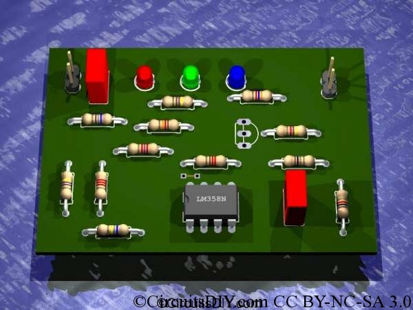
There are 3 LED on the circuit. One LED will be always on whenever a battery is connected. Another LED will blink continuously to indicate charging and the third LED will glow when battery charge complete.
We can charge these Li-ion battery packs with direct regulated voltage but these batteries require special charging technique for long lasting.
These are than when battery charge is less than 20%, charging voltage should be low, not a constant and when battery is full, i.e, charging current almost zero, charging should stop.
In this circuit, the both conditions are checked with the 1R resistor which is in series with the battery.
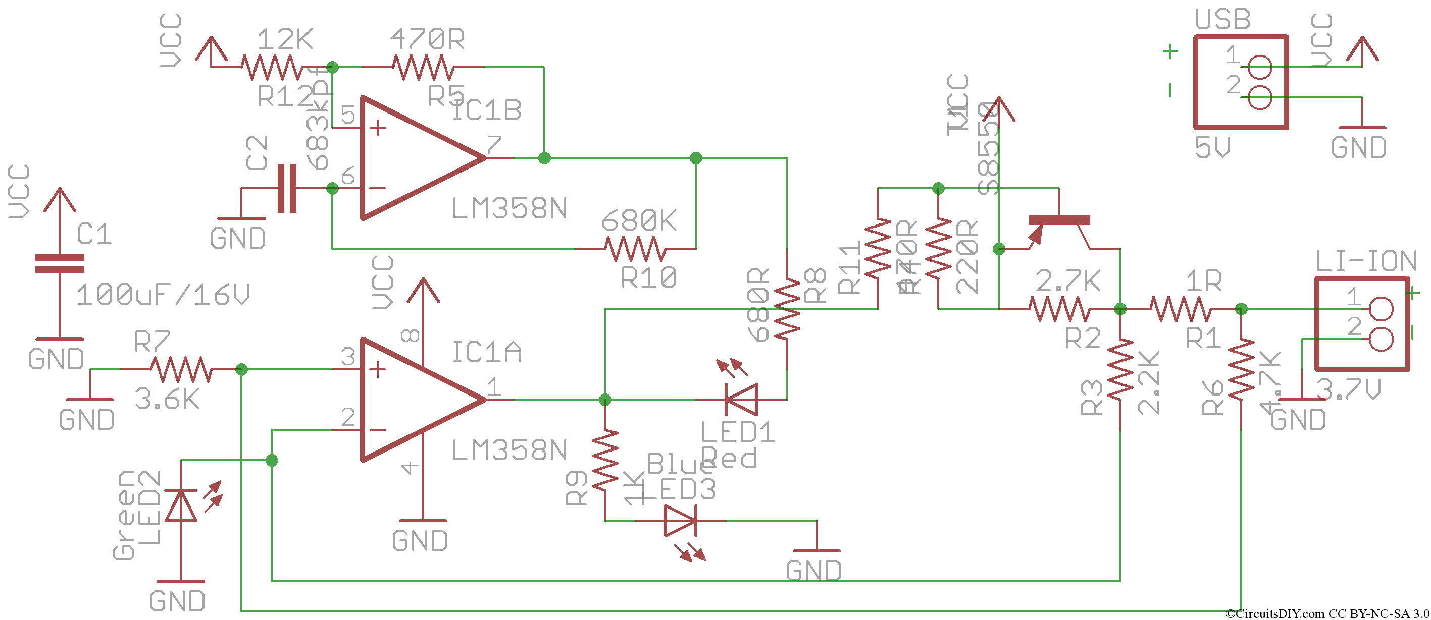
You can connect USB port’s 5V supply here, and also can connect any other 5V supply.
Hi!
I did construct this circuit this circuit and well it sort of worked.
I had a Li-ion that needs to be charged and did connect it and the red light appear but did not flash. Once the red light went off the blue led came up. But it lights up even if i remove the battery. And the green light stays on all the time. Overall all the leds are very dim when they lite up.
This circuit was very easy to build and i like the simplicity its just that i cant get it to work. Oh! and I changed the S8550 to a TIP32c because it draws a heavy current when charging.
well appreciated circuit and glad if you can help me to point out how to overcome the errors.
Thank you
Hasantha Pieris
Hi Hasanta,
When I looked the circuit at first glance I noted some problems like the incorrect configuration of the astable oscillator used to make the LED1 blink under charging. This configuration only works using symmetrical power source but is possible make a simply modification to work with single power source. The LED2 was placed inverted and never will turn on and the resistors to limit the current in the LEDs are wrongly calculated. Even so the rest of the circuit was correctly configured and I made one analysis performing some calculations to check if the resistor values were according to ensure correct values of charging voltages and currents. If they are not correct the battery may explode! So I raised the battery from 20% to 50%, 70%, 90% and 100% and also used a circuit simulator program to check the values. Since the S8550 doesn’t exist on the simulator library I need use the BD136 instead but it doesn’t change the results.
The values of the resistors around the transistor are correct and the ones of the voltage divider from the battery to the non-inverting input of the OP are also correct but I suggest change the 3k6 resistor by a series association of a 3k3 and 330 Ohms resistors. Using them the battery voltage will be limited up to 4V. Well, let’s make the LEDs bright well! Change the value of R8 to 220 Ohms, R9 to 180 Ohms. Invert the connections of LED2, I.E. the anode should be connected to the inverting input of IC1A and the cathode to ground and change the value of R3 to 220 Ohms. Please note: with the actual configuration the astable oscillator made with IC1B the LED1 will not blink! If you wish you can eliminate this part of circuit and connect R8 (with the correct value) to +5V use a 741 (single operational amplifier) instead of the LM358. But if you want let the blinking feature please contact me using the email ******@yahoo.com and I will send to you the right circuit configuration.
Best regards,
João Roberto Gabbardo
Thanks for pointing out the drawing error in LED2.
Actually this circuit is from combining few Li-ion chargers' circuitry together. It does work for me and yes, the blinking LED brightness is very low.
It would be much appreciated if you can make a better version using a LM741.
Can you send me the circuit of blinkin feature to the e-mail ??
Thaks!
Hi Joao, can you send me the circuit of blinkin feature and 741 version to the e-mail?
Thaks!
Dear Joao:
Can you send me the circuit u mentioned above using Altium? I would like to do some simulations on it.
Thank you very much for yr help!
Hi Hasanta,
You are welcome! I think the author placed the LED wrongly when was drawing the circuit although the current limiting resistors for the LEDS seems to be wrongly calculated. Calculate them is very easy and you only need use the Ohm’s law. By first choose the current you want flow in the LEDs. Values from 10 to 20mA are fine. Now subtract from the voltage source available to them the LED voltage drop – to LEDs red, green and yellow you can use a value of 2V and to white and blue LEDs use 3V. Now divide the result by the current and you will have the resistor value. Choose the nearest commercial resistor value. Concerning to the simplified version using the 741 or even a version using the right astable oscillator, please inform your email or write a message to email informed by me and I will send to you the circuits.
Best regards,
João Roberto Gabbardo
hey João
please send me correct circuit to my e-mail is depicted here. or on *********** thanks.!!
Hi João Roberto Gabbardo,
Any update on your circuit? Maybe you could upload it to a hosting site and link it in here. I'm also interested on your version of the circuit.
Thanks,
Keith Beja
hi every one how could i get correct schematic and blink led?
thanks
Just reverse LED2.
hi
thank you for reply
i create this charger and work perfect but led1 do not blink
how could i get it
thanks
Is this for battery packs or for single cells ?? (single cells that are not attached to any circuit).
thanx
Hey João Roberto Gabbardo,
Would you mind sending me the correct version of the charging circuit? much appreciated!
Thank you very much!
Thanks Arup for the good work, helping with lot of circuits.
Is it possible to give the circuit diagrams with more size and clarity.
Thanks.
Yeah. Check homepage for recent version.
hi there, would you be so kind to send me the updated circuit so i could try it out..
many thanks
jez
hi
how could i change circuit for 3.7v 2.4a battery?(please help)
i found one way to get blinking led . you can increase voltage to 6v .
thanks
Would you mind sending me the correct version of the charging circuit? much appreciated. please tell me how to design these resistors values ? because I want to use it for Li-ion Battrery (3.7V)...hope you can teach me this knowage ....thx a lot
Use a pot in place of resistor and increase/decrease value and observe change in output voltage and other things. Simple.
It is extremely dangerous to tickle charge Lithium battreis as they may explode.. In your circuite the 2.7k(R2) resistor will charge battery even after the trasistor is open after full charge. This may be OK for other type of battries and not for Lithium. My opinion , this resistor is to be omitted My coment only pertains to resistor R2 and it doesnt say any thing abt the rest of circuite..
gd work. how can I alter the charging current & circuit for 8.4v li-ion pack?
Can we change this circuit to charge 6V 4.5Ah battery if yes how?
Thanks In Advance.