There are basically three types of Inverters in the market. These are,
- Squarewave Inverter
- Sinewave Inverter
- Modified Sinewave Inverter

Waveform Comparison
Most of the inverters in the market uses modified sinewave for better output at competitive cost. The modified sinewave unit uses a 50% fixed PWM squarewave and the hikes are balanced by a capacitor to produce almost a sine wave. This is called quasi sinewave having THD around 25-28% while squarewave inverters have 45% THD and pure sinewave inverters have just 3% THD.
So, to form a modified sinewave inverter of 220V, we have to generate a 4 phase signal which has 25% 0V, 25% +311V, 25% 0V and 25% -311V. Thus, by series resistor-ed capacitor, the waveform becomes a quasi sinewave. In the driving section of push pull MOSFET sets (2 sets) we have to provide the following pulse,
MOSFET set 1: 0,1,0,0-0,1,0,0-0,1,0,0…
MOSFET set2: 0,0,0,1-0,0,0,1-0,0,0,1…
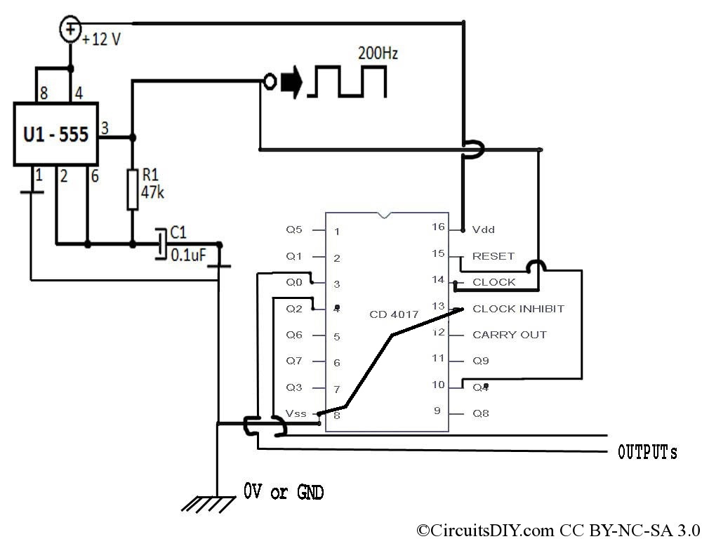
Now this requires a controlled bistable multivibrator whose output is set to off in 50% time. But we will use here a simple replacement for that. It’s a 4017 decade counter IC. We’ll use it to generate 4 pulses and the fifth state would be reset and this creates our required pulse. Then we just connect two non-consecutive outputs to MOSFET section to generate output. But there’s a tricky part in the clock and frequency. Since 4017 decade counter IC don’t have inbuilt clock generator, it requires external CP. For this we’ll use 555 timer IC and for each CP the output changes one step, but we need 4 changes for a complete 360° cycle. Hence, to make a 50Hz output, we need to set 555 timer IC to 200Hz.
Please note that following circuit only shows upto outputs from oscillator, you need to connect MOSFET pairs at the outputs for driving the Inverter Transformer.
Thus the circuit becomes as follows.
Leave a Reply