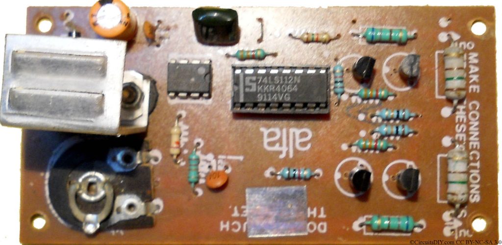
I’ve found this board in many inverters, and it works great with transistor type inverters. I have tested this kit with Mosfets, but the gate triggering was low, and had to be followed by some emitter follower network for proper operation.
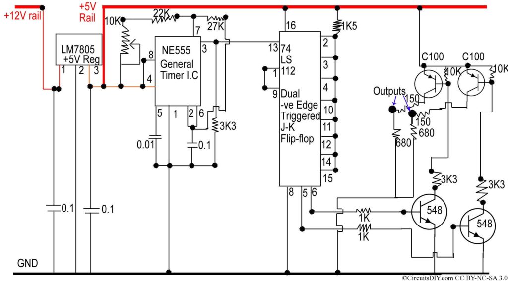
This types of kits are very simple. Let’s check out it. This kit consists of main 3 IC’s. They are LM7805 +5V0 Regulator IC, that is used for digital signal passing.
Second one is a NE555 Ic, which is a widely used clock pulse generator. The third IC is 74LS112, which is dual -ve edge triggered JK flip flop. This changes state depending on clock pulses here. It is used to only toggle at -ve or falling edge as it’s all inputs (J1,J2,K1,K2) are set to logical 1 or high by a resistor to the +ve source.
The toggled output generates two opposite signals say Q and Q’ . They are then sent to a transistor (TTL) level amplifier to generate more strong signal.
The transistor network is made by 2 transistors each section, as C100(pnp) and BC548(npn). The overall output is then fed to the transistor power section of the inverter.
Pros.
- High stable and frequency controllable oscillator kit
- very cheap components and easy design
- Can also work with MOSFETs with a little modification
Cons.
- This is a square-wave oscillator, so inductive loads cannot run properly by this type of inverter
- This being a squarewave oscillator, we cannot control PWM of it, and also can’t control power output by any input condition.
This kits are priced around 70-80 rupees only for good brand as ‘alfa’. Either buy a complete board, or make on vero, the item is as simple as it is.
Can I make a modified sinewave inverter with this board?
I have bought this board thinking it to be a modified sinewave output. Now I am getting to know that it is a square wave type. Can I make a modified sinewave inverter with this board?
Look at the below link for the solution.
What an awful circuit is that , why that way ?
I agree that it is simple , but it is improper way too .
Best Regards
Ali
what will be the power output
i need a sine wave generator circuit in working condition,i saw a lot of circuit on net but none of them give me sine wave,
i need sine wave generator circuit because for SPWM i have to compare sine wave and triangular wave. please help me and send sine wave generator circuit in working condition on y email i.d:
You can have a sinewave generator circuit by using Op-amps.
eg. http://www.onegentleman.biz/Hardware%20Design/Op-Amp%20Oscillators/Osc%20Pics/fig-2.jpg
hi mr Arup, i'm rilly great ful for your posting, i am a fan of electronics, please could u least the parts of this power inverter?
hai ur explanation was good .can i use a 6v lead acid battery?
Great info on heatsink construction, i also go overboard on extra aluminum.mosfets like to run cool
hou many houres backup of athat ups and watts hou much
Please how will the battery charge, is there a way it charge automatically and the inverter describe by you, how can we connect the ocillator, please I need practical description. I need your response. God bless
To
Arup
pleas make a charger for 12 v battary can i close transformer sound which one come after on inverter