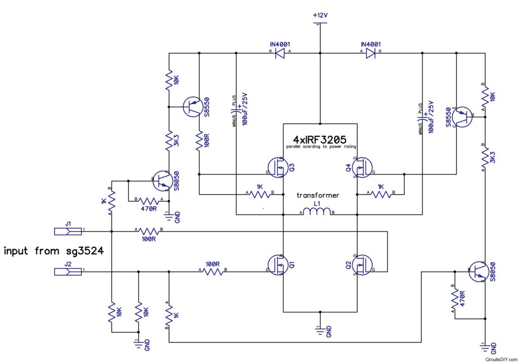
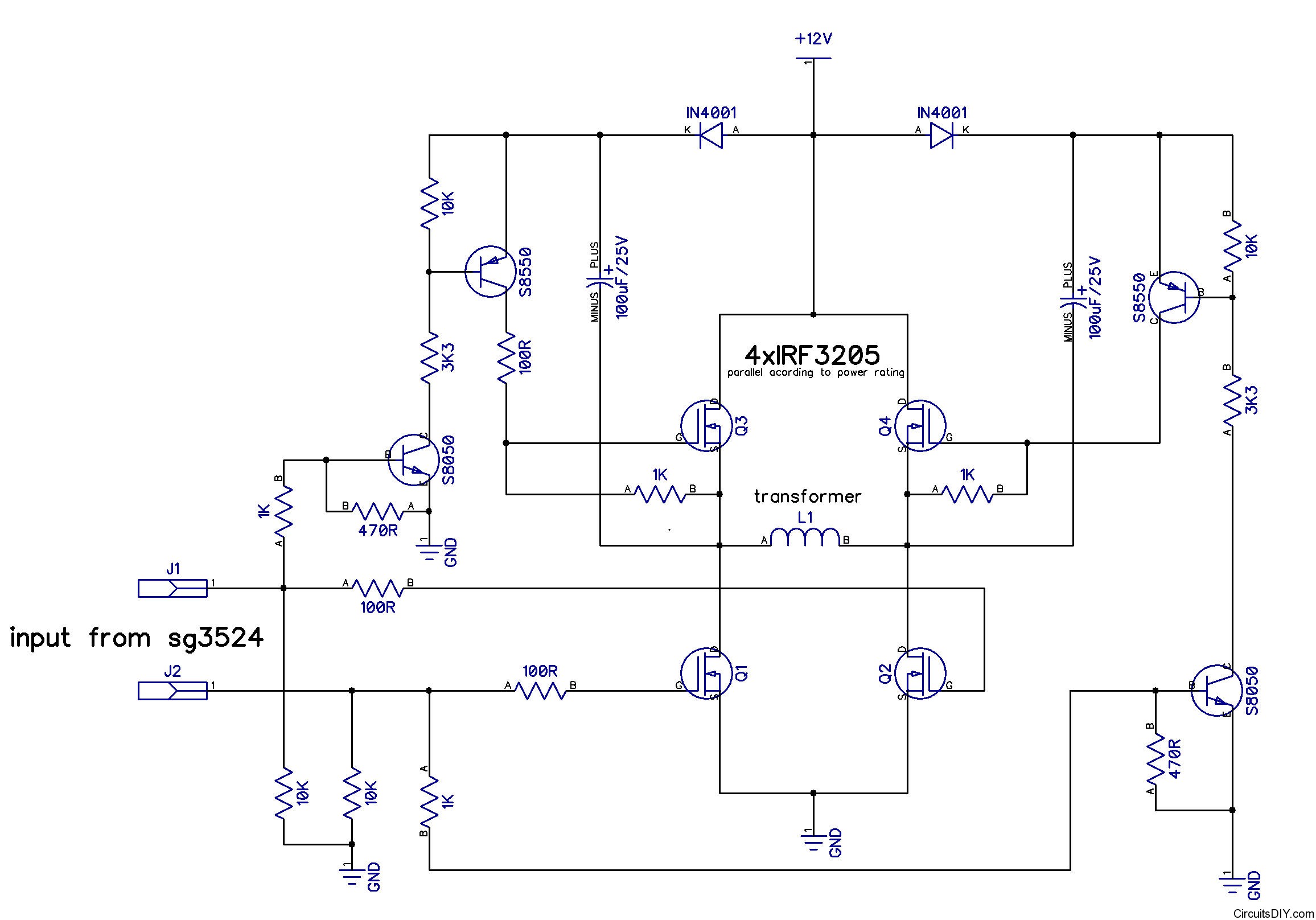
The above circuit I got from replies from edaboard. I had created a thread there on how can I drive a 2 pin primary transformer with H bridge configuration with my SG3524 PWM circuit. I got many replies to use dedicated driver ICs, suggestions to use floating high side gate driver, etc. But I simply needed a solution to run it with circuit made of passive and discrete components and alertlinks gave me this circuit.
This circuit generates a 24V supply from the 12V battery voltage and makes the required high voltage to drive the upper FETs.
The 24V supply is made by a charge pump circuit. In the first two signals from teh SG3524 IC,the alternate 100uF/25V capacitors get charged and it works.


I need h bridge inverter circuit simple 1000watts
Hi Arup, i am new to this forum. pls guide me on using SG3524 oscillator
Welcome, but this is not a forum.
Study the datasheet of the SG3524 IC and see some example circuits by googling for those. You’ll understand it’s working and use.
Thanks for your reply .pls can you post me the circuit for IR2110 driver for inverter. The inverter will be a 12v- 220v, 1000w
Hello Arup.
I like what you are doing and I must say you are a great help for students like us in Africa.
Do you have other mode of payment like LR for donation?
And concerning ? above circuit, will there be modifications for higher power inverters (like 2kva, 3kva, 5kva etc)
Hope to hear from you
Hello Arup.
I like what you are doing and I must say you are a great help for students like us in Africa.
Do you have other mode of payment like LR for donation?
And concerning the above circuit, will there be modifications for higher power inverters (like 2kva, 3kva, 5kva etc)
Hope to hear from you
hello arup sir…
I am an engineeing student and need to make an inverter project.I used four mosfets P55NF06 for bridge inverter circuit,and have made a 555 timer circuit for gating signal to both the pair of mosfet bridge circuit.one pair of mosfet works properly with load but when i connect 2nd pair of mosfet,it gets heated and not work.Is there a need to use different mosfet.
please guide me.
i shall be obliged to you.
and hats off to your work.
saurav.
man that circuit can not work fine the positive fet must bridge with the negative fet,because of the driver,the driver must be on hbridge first with NPN AND PNP transistors
man that circuit can not work fine the positive fet is going to bridge with the negative fet and get bont,because of the driver,the driver must be on hbridge first with NPN AND PNP transistors.
When i was a beginner on inverter job i did things like this,it doesn’t work perfect.I have my own inverter company now in Nigeria which my products are now in the market.pure sine wave hbridge inverter design with PRC PROGRAMMED IC not sg3524
ifyoffordum@gmail.com
ifyoffordum@gmail.com
Onyi, please help me out in this. I’m not an electronic engineer, just a hobbyst. I’m been working on this inverter circuit with ic sg3524. In building the sine wave generator to make the inverter pure sine wave inverter, would the frequency of sine wave generator be the same with the PWM, or higher?
I made my puresinewave inverter using sg3524 and opamp it is very good than micro c,thanks all posted idea in this web.
Please brother what will i do to make it pure sine wave please i need the circuit diagram
Pingback: Simple Output Stage Inverter for Arduino UNO - ElectronicsDNA
Please brother what will i do to make it pure sine wave please i need the circuit diagram
I have built 12v based inverter circuits using this circuit and it worked, however I tried using it on a 24v system, it was humming, heating up the MOSFETs. Is there a way to modify this circuit for a 24v system?. Please help me verify from the source. Thanks