Running inverters on battery drains the battery. This decreases the battery voltage. To regulate output voltage and to make it independent(upto a certain level) we use PWM based drivers like the SG3524 based one. Lets consider the following example:
- Battery capacity: 100Ah
- Battery voltage: 12V
- Inverter load: 500Watts
- Inverter efficiency (avg): 80%.
Now when the battery is full, it will give some 13.5V. When the above inverter is in action at the load, it will draw near 46.3A current. Drawing this much current will make the battery drain in less than an hour.
Assume that after 50mins the battery voltage is 10.5V(almost discharged), then the PWM based one will draw more current like 59.52A. At this time the battery has low charge but the inverter is eating max current out of it.
This can lead to extremely discharged battery if there is no low voltage cutoff protection. It should be mentioned that this types of discharging decreases battery life.
Firstly, low voltage cutoff circuit should have two threshold volts, one for stop and one for start. If it has one volt threshold say,10.5V, then when battery will reach 10.5V it will cut the load, but cutting load will make the battery voltage higher and the load will be on and the load will make voltage lower than 10.5V again and the cycle will go on. For this reason we need two threshold voltages. For example consider the cutoff voltage is10.5V then when the battery goes below 10.5V the load is cutoff, after load if disconnected the battery voltage will increase by 0.1~0.3V, so we need to make the power on threshold voltage to 11V.
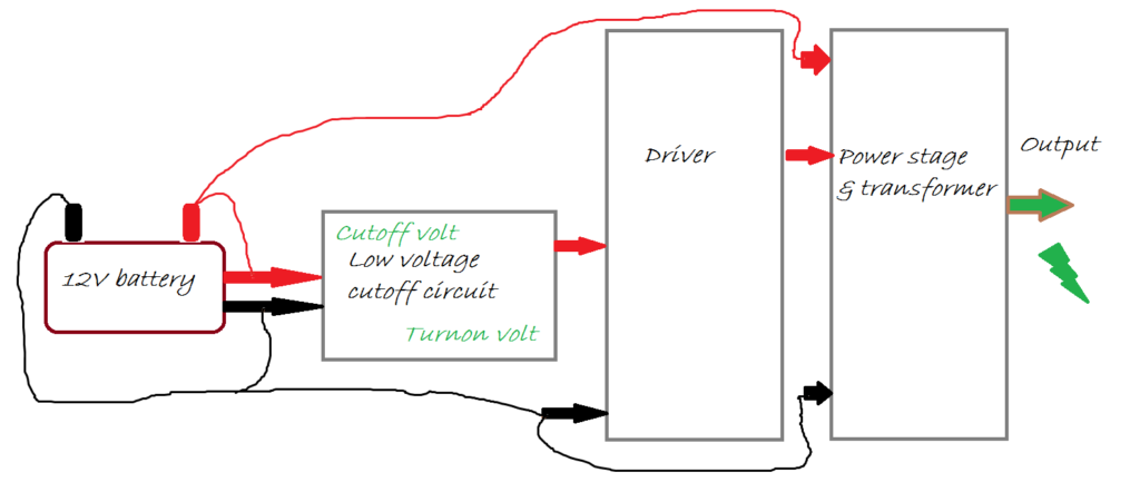
So, the first challenge is to make a device with two threshold voltages one for cutoff another for turnon.
Secondly, an average inverter of 500watts(example above) eats 50-60Amps of current. If we want to cutoff the supply by really, we'll need atleast 60A rated relay which is too expensive. Also, if we use MOSFET with typical RDS(on)=0.015~0.020 Ohm , then at the full load we'll loss near 1V which is near 8% of energy also that will make 50Watt of heat in the MOSFET. So, we need not to dut the supply line for the power stage, bu we need to cut the supply for the driver stage. The driver circuit normally sends positive pulses to activate MOSFET or BJT in the driver section, so we need to cut the supply line (positive) of the driver circuit. Now, a typical driver circuit eats 30mA current, so we can make the switching through a relay as well as through a regular transistor.
The sketch should be as follows.
Work on circuit in progress and will be updated soon.
Leave a Reply